Table of Contents
Example P20: Precipitation simulation during continuous casting of micro-alloyed Fe-Al-C-N-Nb-Ti steel, part 1: Treatment of primary precipitates (MatCalc versions older than 5.61.1000)
Compatibility
MatCalc version: 5.52.0034 - 5.61.0070 (click here if you use a newer version)
Database: mc_fe.tdb, mc_x_FeAlCNNbTi.tdb, mc_fe.ddb
Author: G. Stechauner
Created: 2011-11-23
Revisions: 2013-06-19 (P. Warczok)
Objectives
This is the first of two parts, which describe how to deal with primary precipitates. The method used in this example is thoroughly explained in the 'HowTo' manual for treatment of primary precipitates . It utilizes a virtual heat treatment, to obtain the desired size and number density of precipitates. This calc state is then used for further calculation of the 'real' heat treatment.
Part one starts off with a Scheil-Gulliver analysis to obtain the phase fraction and chemical composition of the primary precipitates. As described in the 'HowTo' manual, an equilibrium calculation is performed subsequently to evaluate a suitable temperature for the heat treatment. The optimal time and temperature for the heat treatment and the precipitation parameters are determined empirically.
With this method, an adequate calc state is found, which can be used for further precipitation calculations.
Part two will continue with the calculation of precipitation in enriched and depleted regions.
Related documents
- 'HowTo' manual - Primary precipitates
Complementary files
Click here to view the script for this tutorial.
Main document
Consider the same microalloyed steel as in example E20. The following table summarizes the chemical composition of the steel used in this study. The nominal composition is given in wt%.
| C | Al | N | Nb | Ti |
|---|---|---|---|---|
| 0.22 | 0.025 | 0.0061 | 0.036 | 0.0081 |
Setup thermodynamics
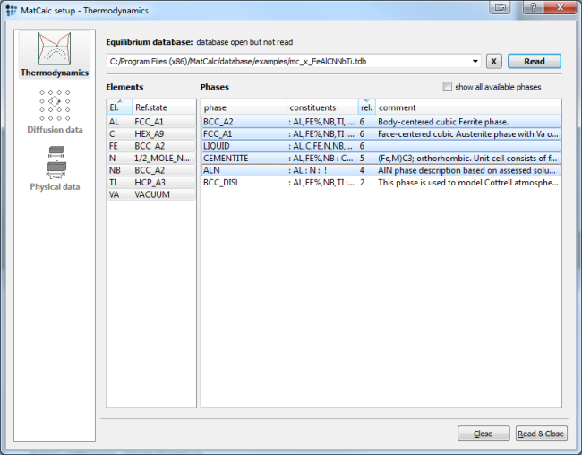
For simulation, either the 'mc_fe' or the 'mc_x_FeAlCNNbTi' database can be used. The dialog below shows the selected elements and phases for the 'mc_x_FeAlCNNbTi' database:
Open the database, select elements and phases, and read the database. Further load the diffusion database for Fe, as it is needed in precipitation simulation. Then enter the composition of the system in the 'Composition …' dialog of the 'Global' menu according to the table shown above.
Setup phases
With the selection of the FCC_A1 phase, MatCalc automatically creates a complex carbo-nitride if Nb and Ti as well as C and N are selected. This complex carbo-nitride shows a miscibilitiy gap, however, which must be taken into account in the simulation setup. This issue is dealt with extensively in example E3 - Analysis of the miscibility gap in Fe-C-N-Nb-V. The carbo-nitride phase FCC_A1#01 is separated into two phases in the following steps: Suspend the original complex phase. Create composition sets for the miscibility gap phases.
Open the phase status dialog window and suspend the automatically created FCC_A1#01 in the 'general' tab. Select the FCC_A1 phase and create a composition set by pressing the 'Create…' button. Select 'composition set', instead of 'equilibrium'. Enter :NB%,TI:C%,N,VA: as constituents for NbC and name it correspondingly. Repeat this procedure for TiN and define the constituents and major constituents (by setting the %) appropriately (:NB,TI%:C,N%,VA:).
Evaluate phase fraction of primary precipitates
Perform a Scheil-Gulliver analysis to obtain the values for phase fraction and chemical composition of primary precipitation phase. Refer to E20 if you want to refresh your knowledge about this method.
Choose a temperature of 1570°C to start the Scheil simulation in the liquid phase. Allow back-diffusion of C and N and run the calculation to a minimum liquid fraction of 3% (enter as 0.03).
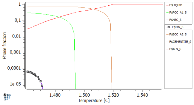
Plot the liquid and Scheil-Phase fractions in an X-Y plot. After renaming, rescaling, and zooming in, a figure similar to the one below should be obtained.
The easiest method to extract the chemical composition of the solute-enriched region now is, to open the Buffer states window (Ctrl + L) and select the temperature corresponding to 3% residual liquid. This is generally the lowest temperature, or the one above it. In our case, we use the temperature of 1462C as the phase fraction of liquid is closer to the 3% compared to the values obtained at 1461C.
Phase fractions obtained at 1462C:
#### /LIQUID/ moles: 0,0305076, gm: -101295 (-101295), sff: 1
Phasestatus: entered - active
FE +9,52351e-001   C +4,18904e-002  NB +4,28714e-003  TI +7,14451e-004
 N +5,35481e-004  AL +2,21249e-004

#### /TIN_S/ moles: 5,64144e-005, gm: -226949 (-226949), sff: 0,500378
Phasestatus: fixed
dfm: -9,46075e+000
TI +4,94450e-001   N +4,46308e-001   C +5,33139e-002  NB +5,92815e-003
Now that we know the phase fraction and chemical composition of the primary TiN, we can start to build our virtual heat treatment.
Important note …
Setting up the precipitation system
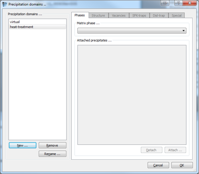
Close the MatCalc workspace, as we do not need the Scheil analysis any longer. Create a new workspace and set up the thermodynamic system as before. Create two precipitation domains: 'virtual', for the virtual pre-heat treatment, and 'heat-treatment', for the real one.
Continue by defining the precipitates:
- In the phase status dialog, suspend the automatically created equilibrium phase
FCC_A1#01. - Create a new equilibrium phase
FCC_A1#02(Used as the precipitation domain for virtual heat treatment) - Close the 'phase status' dialog and open the 'precipitation domains' dialog.
- Select
FCC_A1#02as the matrix phase for virtual, andFCC_A1as the matrix phase for heat-treatment. - Close this dialog and open the phase status dialog anew.
- Create a new composition set based on
FCC_A1with the following constituents::NB,TI%:C,N%:and name itTiN. - Create a new composition set based on
FCC_A1with the following constituents::NB%,TI:C%,N:and name itNbC. - Create two precipitate phases for
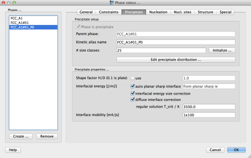
TiN(primary and secondary) and one each forNbCandAlN. - Enter the following values in the 'precipitate' tab of the 'phase status' dialog:
| Precipitate | TiN_p0 | TiN_p1 | NbC_p0 | AlN_p0 |
|---|---|---|---|---|
| # Size classes | 25 | 25 | 25 | 25 |
| prec. domain & restrict nucl. to | virtual | heat-treatment | heat-treatment | heat-treatment |
| nucleate only with valid major const. | ✔ | ✔ | ✔ | ✔ |
| nucleation site | grain bound. edge | bulk | bulk | bulk |
| Incubation time constant | 100 | 1.0 | 1.0 | 1.0 |
| Diff. in prec. as ratio of matrix diff. | 1e-15 | 0.01 | 0.01 | 0.01 |
Note that the settings for the virtual heat treatment can be arbitrarily chosen and are not necessarily 'physically justified'. They are only aimed at reproducing the correct size and composition of the primary precipitate(s) with minimum computational effort.
- Close the phase dialog as the system is now set up.
Setting up the virtual heat treatment
As already mentioned in the 'HowTo' manual - Primary precipitates , the values which are used in this step are absolutely arbitrary. If a heating rate of 10000K/s followed by annealing for 100 years at 1000°C leads to the desired size and number density of the primary precipitates, that's fine! The only limitation one should keep in mind, is the correctness of the obtained values for size distribution, phase fraction and chemical composition; and the minimization of computational effort. Minimization of calculation time in the virtual heat treatment can be achieved by ensuring that the precipitate evolution is finished before onset of the coarsening regime, where the shrinking and final dissolution of particles takes place. This process is time consuming in the simulation. If this happens, set up the parameters such that a smaller number density of precipitates is obtained.
Because primary precipitates are rather big, we are usually trying to achieve a size of a few µm, with a phase fraction and chemical composition similar to the Scheil analysis.
To get an idea, at which temperature to anneal to achieve the desired phase fraction, make an equilibrium calculation beforehand. A temperature of about 1415°C is appropriate to precipitate TiN with the target phase fraction of 5e-5.
The process of finding the optimal variables is best described as trial and error. The following procedure is found to be suitable:
- Open the 'heat treatment' dialog.
- Create a new HT called virtual, and append a new segment.
- Enter a starting temperature of 1110°C, and anneal at this temperature for 100 seconds. Select 'virtual' as the precipitation domain.
- Append a new segment and heat the sample to 1405°C with a heating rate of 1K/s.
- Append a new segment and anneal at this temperature for 1e+07 seconds.
Setting up the graphical output
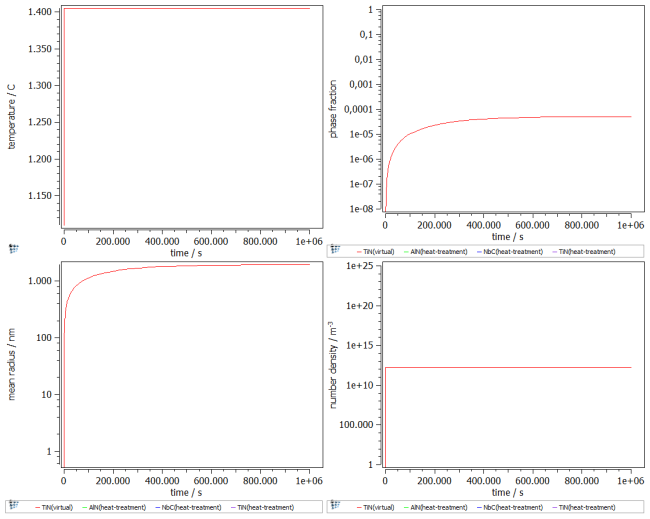
To follow the growth of the precipitates during the heat treatment, a plot is needed. Create a p1 plot window with 4 plots and plot T$C, f_prec$FCC_A1#01_p0, num_prec$FCC_A1#01_p0 and r_mean$FCC_A1#01_p0. Change the scaling and title of axes according to the figure below. Alternatively, run this script to set up the windows accordingly.
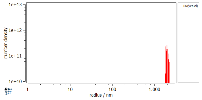
If you are interested in the size distribution, create a histogram and plot the primary precipitates.
Starting the simulation
As everything is configured, the simulation can begin. Open the 'Precipitation simulation' dialog, and select the virtual heat treatment as the temperature control. Then press Go!
Result
The figure shows the result of the simulation. A phase fraction of about 5e-5 with similar chemical composition to the Scheil analysis was achieved. Save the Calc State, and use it for further simulations.
Transfer of precipitate distributions
Save the workspace file as P20_1.mcw.
Once we have generated the size distribution for the primary precipitate, we can export the size distribution into a file to be able to read it back into our system in the further simulations. To do so, open the 'phase status' dialog in the precipitate tab.
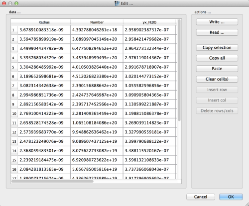
Click the 'edit precipitate distribution' button.
Use the 'Write …' button to export the size distribution into a text file. Give it the name 'size_dist_tin_primary.txt'.
Alternatively, you can save the size distribution using console command:
EXPORT_PRECIPITATE_DIST tin_p0 size_dist_tin_primary.txt
Consecutive articles
This analysis is continued in part 2 article Precipitation kinetics in segregated and depleted regions
